
Manual Layouting in Designer - Quick Reference Guide
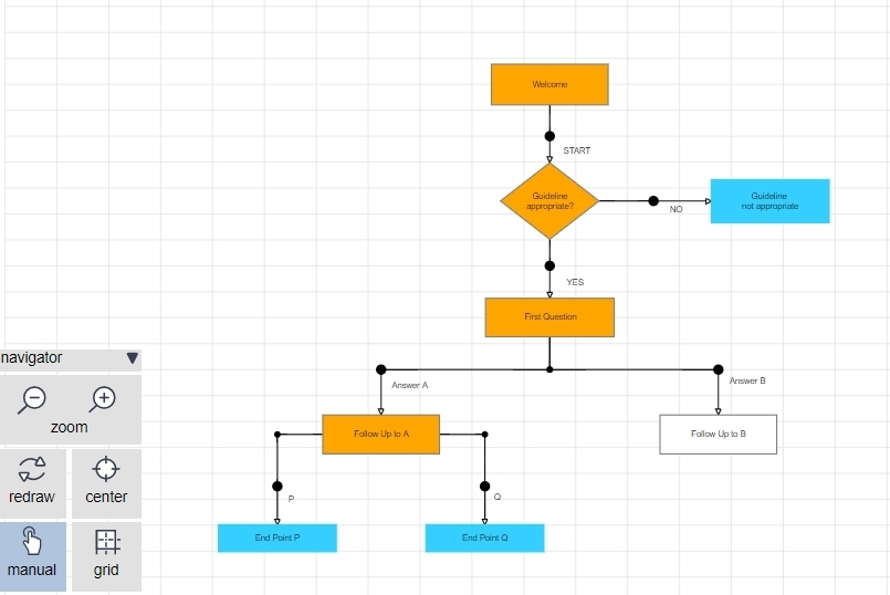
Below are some of the common tools you can use when laying out visual guidelines.
| Main Canvas | ||
| Toggle manual layout mode on/off |
 |
Enable or disable the manual layout mode by clicking the manual button on the navigator menu at the bottom-left of the canvas. |
| Drag the canvas to reposition the logicnet |
 |
To move the canvas, left-click your mouse and continue holding down the mouse button while moving the mouse. Release your mouse button to complete the action. |
| Zoom in or out |
 |
Use your mouse wheel to zoom the logicnet in or out, or use the zoom icons in the bottom-left menu. |
| Enable grid lines |
 |
You can enable or disable the grid lines by clicking on the grid button from the navigator menu at the bottom-left of the canvas. |
| Center the canvas |
 |
You can center the logicnet on the canvas by selecting the center option from the navigator menu at the bottom-left of the canvas. |
| Linking Nodes | ||
| Add a new link |
 |
Right-click on a node and select the add link option from the menu. The system attaches a link to the node you select. Using your mouse, left-click on the node to which you want to connect the link. If a node has output options (the route on output setting in the node part editor), first select the output option you want to connect to the subsequent node. |
| Delete a link |
 |
Right-click on a link and select the delete option from the popup menu. If a link has output selectors, select the section of the link that has the arrow head attached to it to see the delete option. |
| Add an elbow joint |
 |
Left-click on a link and the system displays a white circle in the middle of the section of the link you clicked on. Left-click on the white circle to add the joint. Then select the joint and drag it to where you want it, keeping your left mouse button down until it is located over the target node. |
| Change the position of an output label |
 |
Select and drag the output label text to any other position by pressing your left mouse button and moving your mouse. Let the mouse button go when the label is positioned where you want it. |
| Change the text of an output label |
 |
The system automatically generates output labels based on the Values field of the Options table in a radio list. In the part editor, navigate to the Advanced tab and provide alternative display labels for one or more specific output selector options. Check the Only use Display Label for connectors option to use display labels (including blanks) for all outputs. |
| Node Layout | ||
| Select/copy/delete a node |
 |
Using your mouse, left-click on a node. When a node is selected any of the menu bar options apply to the selected node, including copy/delete, add a new node, and connect to selected node. |
| Add a new node onto an existing logicnet |
  |
There are three ways you can add a node onto an existing logicnet.
|
| Reposition a node |
 |
Drag a node to its position by left-clicking on the node and dragging it to its new position. The canvas automatically scrolls if you come close to the edge of the canvas. |
| Snap a node to the grid |
 |
When you move a node, the system automatically snaps it to the grid. You can also move a node by using the Shift+Arrow keys on your keyboard. For non-snapping moves and making small position changes, use the Ctr+Arrow keys on your keyboard. |
| Change the size of a node |
  |
Move your mouse over the right edge or bottom edges of a node and the system displays the resize arrows. Left-click on the edge and drag the edges of a node to change the width and height. You can also right-click on a node and use the option in the popup menu to set the exact width and height of a node. |
| Change the shape of a node |
 |
Some part editors include an option to change the shape of the node. For example, if you add a radio form part you will see a dropdown menu near the bottom of the part editor with the label shape. This menu allows you to set the node shape to rectangle, diamond, or hexagon. |
| Change the label of a node |
 |
You can change the label of the node in two ways:
Note: For long labels the system automatically calculates line breaks only if you did not add breaks manually. |
| Open a node/part editor |
Double-click on a node with your left mouse button. |
|
| Close a node/part editor |
Double-click on the canvas/graph. |
|
| Open node/part menu |
Right-click on a node. The system displays the full menu of options, including add links, edit label, and other common options. |
|
Reply
Content aside
- 4 yrs agoLast active
- 50Views
-
2
Following