
Visual Navigation Example Project
In this example project you will learn how to create a project that uses the Visual Navigation framework. It goes over the basic steps to add the project to your Designer workspace and shows you how to add nodes and resources to nodes as well as how to connect to logicnets within your project.
Log in to your LogicNets Designer workspace to start this project and follow the steps below:
Add a New Visual Navigation Project

1. Click the projects folder in the folder tree on the left.
2. Select the blue folder with the + icon to add a new project.
3. Select the VGN option from the Project Templates
4. Fill in a name for your project.
You will see that the system created a new blue folder in the projects folder you had selected previously.
Navigate to the Start Node

1. Expand the new project folder that has the name you just provided in the previous step by clicking on the arrow pointer before the blue folder. This will show you the sub-folders. As you can see the system created a folder structure with several sub-folders.
2. Click on the arrow before the logicnets folder to expand this.
3. Click on the logicnet called start. This is the logicnet that is shown first when you start the project later.
Modify the First Node

1. Notice that you can drag the canvas with your mouse by holding your left mouse button down and drag the canvas. This canvas mode is set to manual layout, that means that the positioning of the nodes is done manually as these will be shared with the user when they interact with the final application and see the node structures. Also the grid lines are enabled by selecting the grid option.
2. Double-click the orange node to see the part editor appear on the right hand side. Nodes can consist of one or more parts (an example of a part is a radio-list question). If there is only one part the part editor opens up directly.
In this example we are going to change the values of some of the following properties for this part. This initial part is a radio-list question. That means that when the user is presented with this question, they can only select one of the presented answer options.
3. Caption should be changed to What will the weather do today?
4. Data object should be changed to weather The data object is required, and can be used elsewhere to "lookup" the answer that the user gives.
5. Submit on Select sets the property to automatically go to the next node when the user select the answer option.
6. Route on Output makes the system add different outputs for each of the answers that the user can select.
7. Enter the the options that the user can select from. Each answer option has a value and a caption. The value is what the system stores in the data object when the user selects this option. The caption is what is presented on screen. These can be the same, but they don't have to be. Note that in this example the captions are capitalized and the values are not. (It's a good idea to keep all your internal variables lowercase). You can change the options by selecting the modify button next to each option. Select save next to each answer option when you are done with the changes for one item. Then you can edit the next, and so on.
After you've finished editing the form it should look like this.

IMPORTANT: When you are done with editing this part, do click on the save button at the top of the part editor (indicated above).
Change the Node Label
Since the node labels are very visual to the end-users you can change these in the node editor.

1. Right-mouse-click on the node to see the popup menu appear.
2. The second option says form (or node) details. Select that option.
3. Click on the details tab to see the label field.
4. In the label field add the label: weather
Tip: you can add line-breaks for long labels by adding the following characters in the label field: <br/> Placing the line-breaks will cause the label text to print a new line in the visual representation of the node. You can grab the right side and the bottom side of the node to make this visually bigger or smaller.
5. Click the save button to save your changes and see the updated node label.
Add a New Node

1. Left-mouse-click on the arrow down next to the call parts option in the toolbar.
2. Left-mouse-click on the call ->down option and drag the new node on top of the orange node on your canvas.

1. When you drop a node on a node that has set the option route on output you will see the values of the options you defined before. You will need to select to which output this new node needs to be connected. Select the sunny output here.
Add a Call Node
The call node lets you connect your logicnet to other logicnets. This can be used to break large logicnets into smaller and easier to manage components. It can also be used to re-use logicnets that have repeatable logic in them. We selected the call node with the ->down option, this means that the logicnet we are about to connect will open below this call node. The other call node option has ->right next to it. This means that the logicnet will be extended to the right of the call node.

1. The call node is positioned below the Weather node.
2. Add in the field logicnet to call: sunny This logicnet does not exist yet, but we will be adding that shortly.
3. Click the save button in the call node editor.
Manually Position Your Nodes
You can position the nodes anywhere on the canvas to organize your nodes the way you want the user to see these.

1. Left-mouse-click the call node and drag this to the left. You will notice that the node snaps to the grid positions to help with alignments.
2. Left-mouse-click the output selector and drag this to its new position.
3. Left-mouse-click the label of the output selector to its new position.
4. Left-mouse-click on a connector to add a joint. You will first see a white filled circle that you will need to left-mouse-click again to accept the new location of the joint. Once the new joint becomes black you can drag this to its new position.

1. See the new location of the joint.
NOTE: You can add as many joints to a connector as you want. You can remove a joint by right-mouse-clicking on a joint.
Add More Call Nodes
Now repeat the previous steps to add two more call nodes for all the outputs.

1. You can manually position them to look like the image above.
2. Double-click on the two new call nodes and add the names rainy and cloudy in the logicnet to call field of the call node editor (see 3).
Add Logicnets
In this section we will be adding the sunny, rainy and cloudy logicnets that will be called from the start logicnet.

1. Select the logicnets folder in your project folders.
2. Click on the new logicnet icon at the top.
3. Type in sunny in the name field.
4. Click the add button to create the new logicnet.

1. The new logicnet will be opened and you will see a start and stop node because a logicnet opens in automatic layout mode.
2. Change the layout mode by clicking the manual option and select the grid button to show the grid.
Adding the First Node
You are ready now to start adding new nodes to your blank logicnet.

1. Select the down arrow next to the form-parts toolbar option.
2. Select the radio-list option with your left mouse button and hold it down to drag it onto your canvas.

3. When you add a new node, the part editor will open automatically. Fill in the fields as per image above.
Question: Is it warm or cold?
Data object: temperature
Submit on select: checked
Route on output: checked
Options: warm, cold
4. Don't forget to select save after you are done.
Change the Node Label
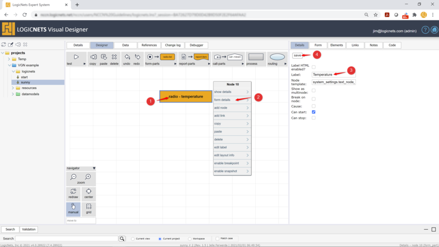
1. Right mouse-click the node to see the popup menu.
2. Select the form details option.
3. Add the label: Temperature
4. Click save
Add a Checklist Node
The checklist node is a special node that shows a list of options to the user where they need to answer each question before they can continue. The options have three states: checked, unchecked and not selected. The last option is important to differentiate between users having answered anything at all.

1. Select the down arrow next to the special nodes group in the toolbar.
2. Select and drag the auc-all node on the orange node.
3. Position the node as per image above.

4. Double click on the node.
5. Fill in the fields as per image above.
Caption: Sunny & Warm Checklist
Data object: sunny_warm_checklist
Options: shorts, sunscreen
6. Select the save button.
Copy and Paste a Node
Adding new nodes can be done quickly by copying and pasting existing nodes.

1. Make sure that the node you want to copy is selected.
2. Click the copy button on the toolbar.
3. Click the canvas anywhere to deselect the node that was highlighted if you don't want to connect the new node to this one.
4. Click the paste button.
5. Drag the new node to where you want to position it.
NOTE: You can multi-select nodes by holding the shift key.
Change the Properties of a Copied Node

1. Select the copied node.
2. Change the fields of the copied node:
Caption: Sunny & Cold Checklist
Data object: sunny_cold_checklist
Options: Change the first option to : gloves
3. Click save
Connect the Copied Node

1. Right-click the node from where you want to connect to the new node.
2. Select the add link option
3. If the originating node has route on output selected, then you will need to select the option you want to connect from. In this case that is the cold option.
4. You can now position the connector and its label correctly and add a joint to straighten out the angles if you want that.
That completes this logicnet. It should look like this:

Test Your Project
Now let's test your project by starting in the mode that a user will see.

1. Click on the project folder.
2. Click on the test button. This will open a new tab or window and shows you what a user will see when they interact with your first Visual Navigation LogicNets project:

3. The user can answer the questions on the left-hand side panel. New questions will appear when the user navigates the pathway.
4. When a question is answered the highlighted pathway is shown on the right. The user can drag the pathway and can zoom in and out. The user can also navigate answer options by selecting these on the pathway directly.
Complete the Project
You can complete the project by adding logicnets for the rainy and cloudy answer options such that the user can navigate these as well. The easiest way to do this is to copy and paste the logicnets and modify the content of the logicnets.

1. Select the logicnet you want to copy.
2. Select the copy button.
3. Select the target folder where you want to copy the logicnet to. Once you select the target folder you will see the paste option at the location where the copy button is.
After you copy it you will have to rename the logicnet.

4. Select the logicnet.
5. Select the Details tab of the logicnet, and select the Modify button (not on screenshot).
6. Rename the logicnet to rainy
Copy the sunny logicnet again and rename it to cloudy. Now you have 3 logicnets for the 3 options in the weather question: sunny, rainy and cloudy.
Add Content Resources
Each node and answer options can be connected to additional content resources such as citations, references or any texts.

1. Navigate to the resources/content folder in your file explorer.
2. Select add content resource.
3. Name the content resource: Sunscreen
4. Resource text. You can copy any text here, for this example we used some text from Wikipedia. Note that you can also link directly to Wikipedia, but that is for a different time!
5. Click save.

Now click on the logicnet that you want to use this content resource in.
1. In the logicnet double-click on the node you want to connect to this content resource.
2. Click on the Resources tab in the part editor.
3. In this editor select a source: content
4. Select the resource from the list
5. Select the Add button
6. See the item show up in the list of connected content resources.
7. (not numbered) click the save button.
Note: You can add multiple content resources to one node. You can also add content resources to options questions parts.
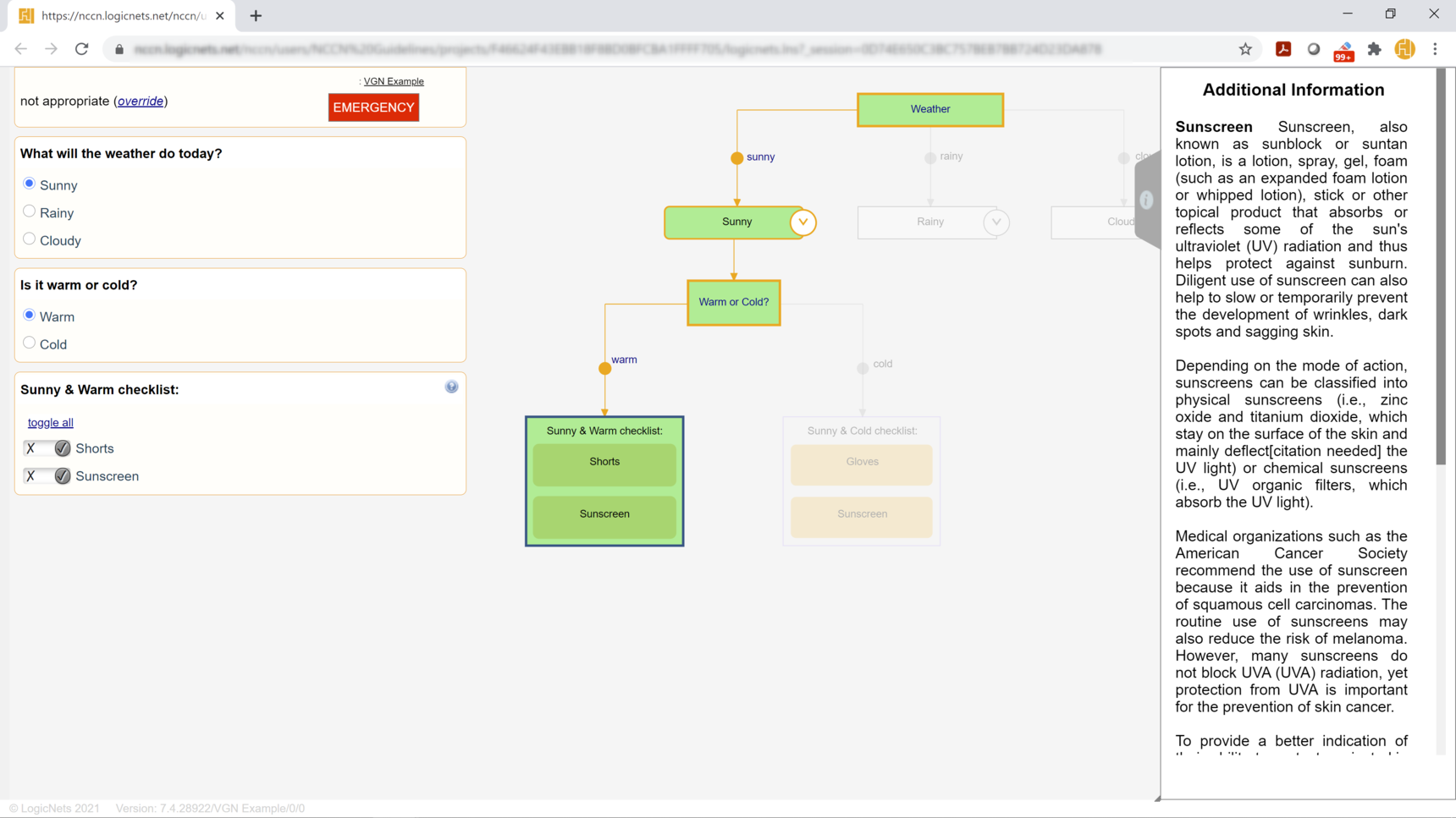
In the users view you will see this when you click the test button on the project folder:

1. Navigate to the question that has the content resource linked to it. Now see that this question has an additional icon.
2. If the user clicks on the icon you will see the information panel slide out from the right hand side with the text from the content resource.
Reply
Content aside
- 5 yrs agoLast active
- 55Views
-
3
Following